NeuroCube
Digital Twin Integration
NeuroCube now has a digital twin for better simulation and testing ( •ᴗ• ).
The Initial Setup
ROS2 Bridge
To enable communication between the physical robot and Isaac Sim, I made use of the ROS2 Bridge provided by Isaac Sim. This allows the physical robot to send vision information (object detection and depth estimation) to Isaac Sim in real-time to process that data and spawn in cubes (as placeholders) for the detected objects. A simplified explanation of how publishing and subscribing works is detailed below:
- The physical robot runs local object detection + depth estimation models to localize objects and estimate their distances.
- Object detection + depth estimation results are then published to ROS2 topics.
- Isaac Sim subscribes to these topics and receives the data.
- Cubes are then spawned in the simulation at the detected locations based on object detection and depth estimates.
Offline Simulation
One of the benefits of working with a digital twin is the ability to bring the twin offline and run “what-if” scenarios without needing to modify the physical robot. This is especially useful for testing and debugging complex systems like navigation and path planning. For example, I do not own any physical LiDAR sensors, so I could test a hypothetical system in Isaac Sim with LiDAR sensors first before investing in the hardware.
Fusing IMU Data
Sometimes, the robot can struggle to maintain accurate localization in environments with few visual features, leading to what’s known as drift, referring to the gradual deviation of the estimated position from the true position. To address this, I integrated IMU (Inertial Measurement Unit) data from the physical robot. In particular, I made use of the IMU’s accelerometer and gyroscope data to provide additional motion cues that help correct initial pose estimates.
Simulating the Physical Robot and Environment
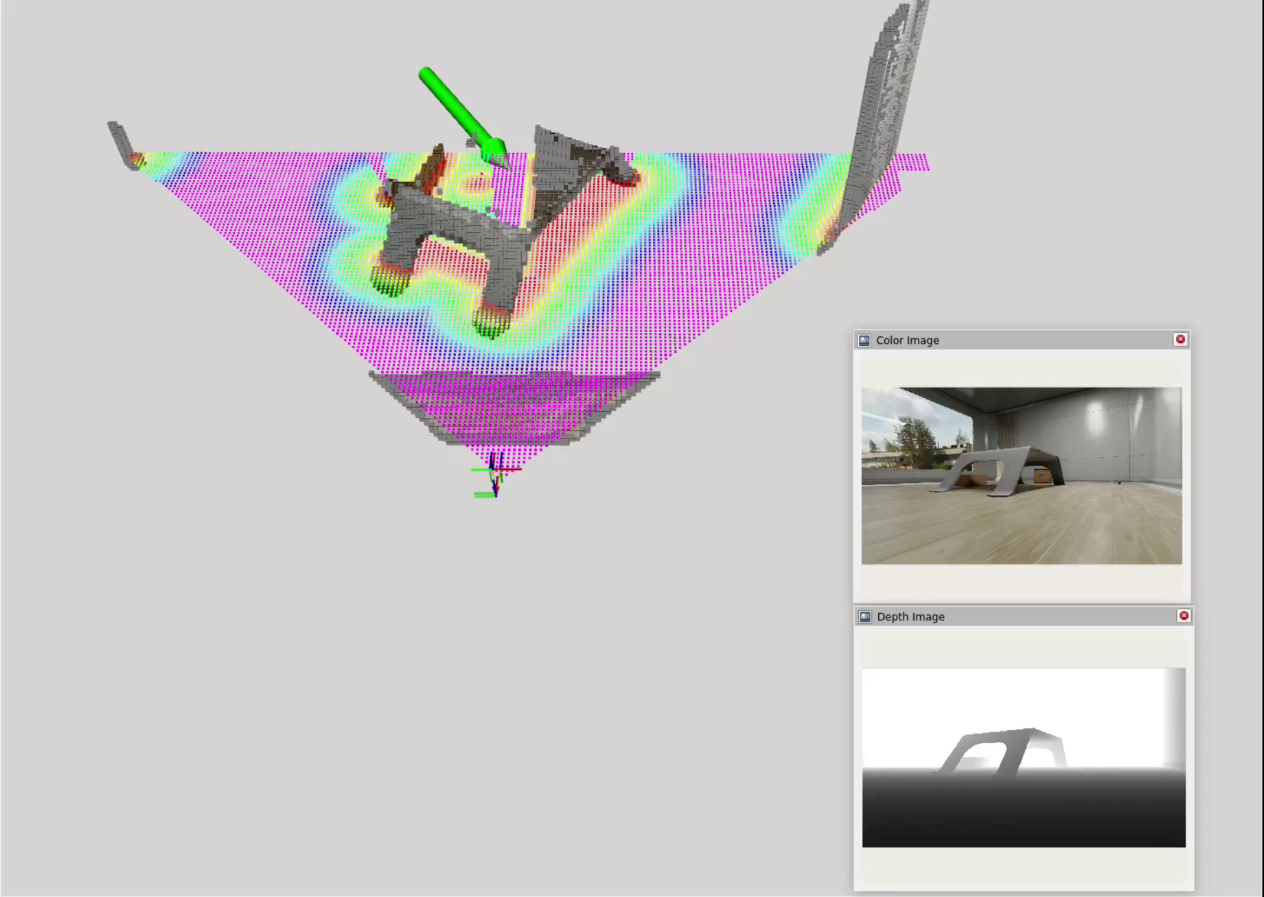
The starting point for the digital twin was to replicate the physical robot and its environment using NVIDIA Isaac Sim. I started with a crude representation of the physical robot and its environment, in which objects detected by object detection + depth estimation models are recreated as cubes in the simulation using the depth map.
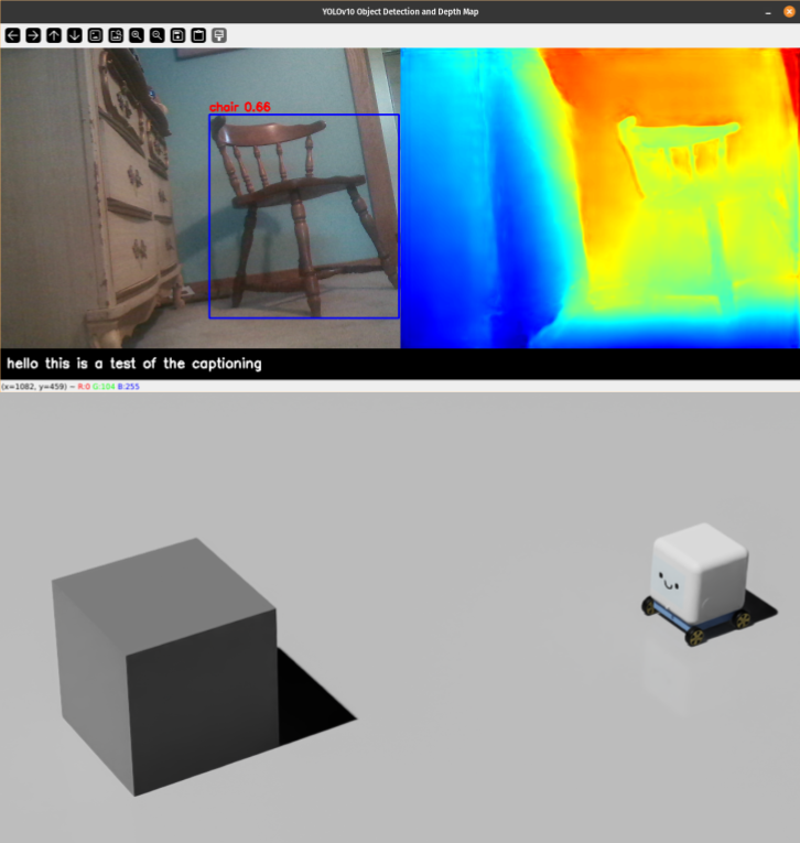
Limitations
Note how objects not detected cannot be replicated in the simulation, which is a big limitation of the setup. The depth map is also quite noisy, leading to sometimes inaccurate placement of the cubes in the simulation (exacerbated by the use of bounding boxes which captures background depths as well). This is mainly due to the limitations of using class-based object detection models and monocular depth estimation models. Objects not learned by the model cannot be detected and a sense of depth from a single camera is inherently ambiguous and noisy.
2D LiDAR and SLAM
To explore alternatives, I tried playing around with 2D LiDAR and Simultaneous Localization and Mapping (SLAM) algorithms in Isaac Sim to create a more accurate map of the environment. The idea is that LiDAR can provide more reliable detection of objects in the environment compared to using vision models alone.
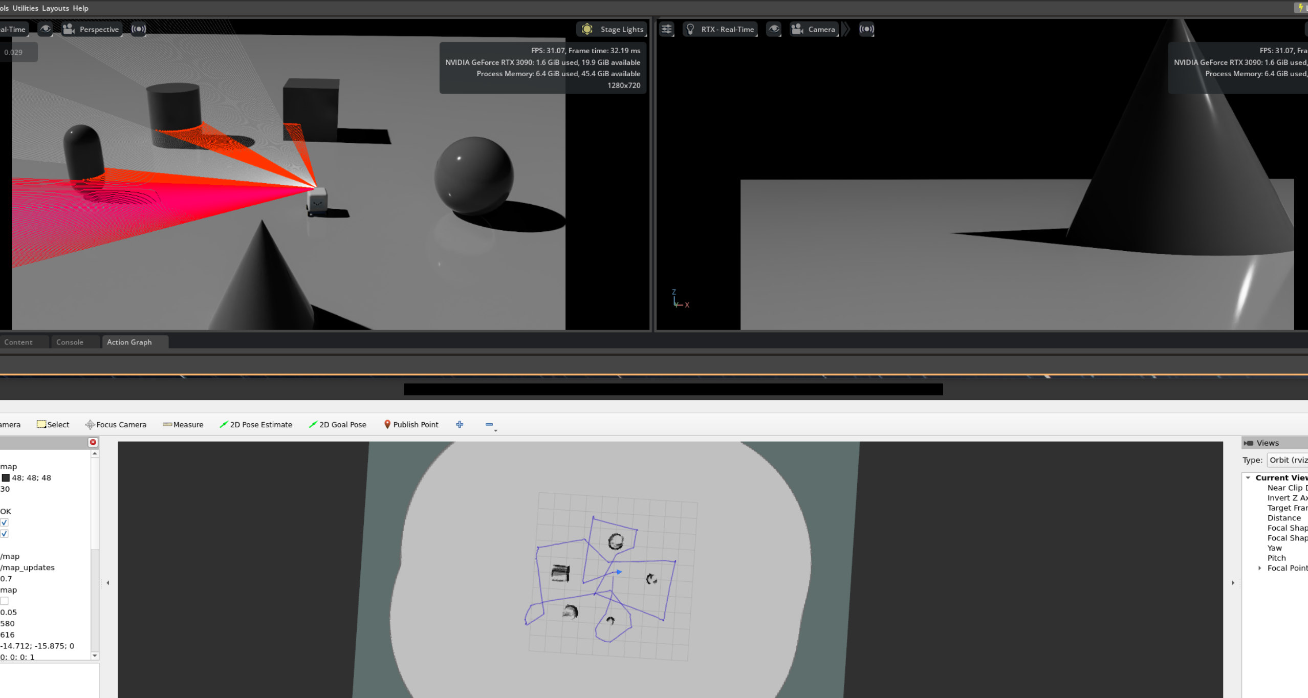
Limitations
The 2D nature of the LiDAR means that objects above or below the scanning plane are missed, leading to potential collisions for missed surfaces. In addition, 2D SLAM works best for flat environments with minimal elevation changes. In more complex environments, it will struggle as ramps may trigger false positives and bumps may destabilize the LiDAR plane on which the map is built. Lastly, fusing data from the LiDAR and camera can be challenging, especially when the fields of view do not match and the data is not spatially aligned (LiDAR - 360 degree horizontal and mounted on top, Camera - 90 degree horizontal/60 degree vertical and mounted at front).
Stereo Cameras and VSLAM
Next, I decided to experiment with stereo cameras and Visual Simultaneous Localization and Mapping (VSLAM) techniques to enable 3D mapping capabilities. Combined with Nvblox for 3D scene reconstruction, we get a much richer representation of the environment:
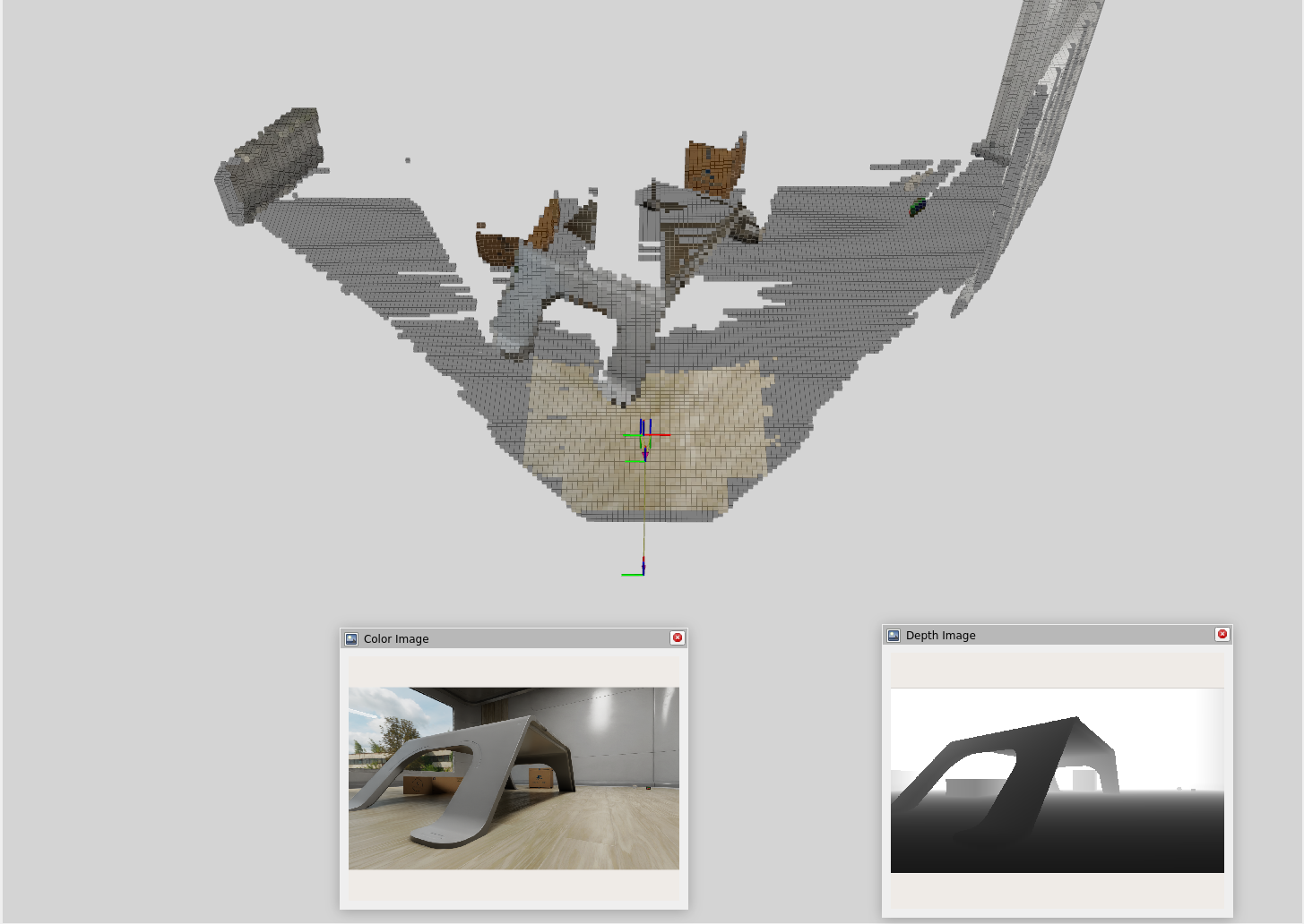
Limitations
One thing to note is that VSLAM can require more computational resources compared to 2D LiDAR + SLAM. The approach is also limited to the front view of the camera, meaning that objects outside the camera’s field of view may be missed unless we implement spin mechanics or use multiple cameras.
Picking a Suitable Approach
| Method | Advantages | Disadvantages |
|---|---|---|
| Object Detection + Depth Estimation Model | Detects and classifies objects using just a monocular camera (simple) | Misses objects, noisy depth estimates, weak mapping capabilities |
| 2D LiDAR + SLAM | Accurate 2D mapping, reliable object detection | Misses objects above/below 2D plane, hard to fuse/align with camera data, some drift may accumulate over time |
| Stereo Camera + VSLAM | Rich 3D mapping, captures more details, camera-aligned map data | More computationally intensive, limited to front view unless multiple cameras are used, severe drift over time unless fused with other sensors such as IMU |
I personally found the stereo camera + VSLAM approach to be the most promising for my use case. It captures a more complete representation of the environment in 3D and can be easily aligned with object detection data, which uses the same camera. Since this approach is limited to the front view of the camera, in my case, I’m planning to have the robot spin around occasionally while exploring the environment to capture a more complete view of its surroundings.
Nav2 and Path Planning
Nav2 is a popular open-source navigation framework for ROS2 that provides a suite of tools for real-time path planning and obstacle avoidance. The idea is to use Nvblox to create a cost map from the VSLAM data and feed that into Nav2 for path planning.
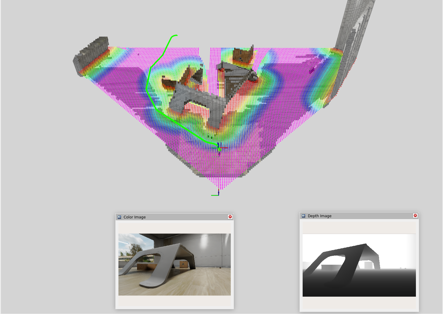
Click and Drag Interface
To test out Nav2, I used a simple click and drag interface to set waypoints for the robot to navigate to. In this interface, I am manually defining a goal position (x, y) and orientation (yaw) for the robot and Nav2 will compute a path to that goal while avoiding obstacles in real-time.
Next Steps
- LLM-based decision making for navigation
- The digital twin click interface allows a human to click and drag at a point of interest to define a goal position and orientation.
- The next step is to implement a task interface that allows users to specify high-level tasks and goals for the robot using natural language.
- Deploying to the physical robot
- The digital twin is a great way to test and validate navigation algorithms in a safe and controlled environment.
- The next step is to deploy the navigation system to the physical robot and test it in real-world scenarios.